Changing Node Order in Vithanco
Estimated reading time: 2 minutes.
The Problem
Laying out a graph depends on node order. The nodes are created in an order and this is the first order used. By maintaining that order Vithanco ensures that the nodes are located where they are and that small changes in the input lead to only small changes in the output. That means that in most cases the leftmost node stays leftmost. The layout algorithms are stable in the sense that they produce the same outcome for the same input. And the order of nodes is part of the input.
And sometimes the original order is not the order you like. You would like the nodes presented in a different order, exchanging two nodes that are located next to each other, or similar.
The Solution
You can change the order of nodes and thus can influence the resulting diagram by using the [TAB] key. Simply select two nodes and press [TAB] and the two nodes exchange their place in the order of nodes. If you select more than 2 nodes and press [TAB] they are rotating their position in the order. Finally, press the [ALT] (or [OPTION]) key at the same time as [TAB] and the order is shuffled.
You can use [TAB] in all diagram types.
Limitations
Sometimes the algorithm will not be influenced by a change of order. 'Good reasons' might keep the layout algorithm from changing the diagram if the order of nodes changes. Examples of these 'good reasons' may:
- to avoid long edges (aka connection)
- to avoid crossing edges, or
- to place nodes within a cluster next to each other,
- to balance a tree based on the next layer (layered view only),
or similar. The above list is not complete and the used algorithms are quite sophisticated.
There are more ways to influence a diagram but these will be captured in another post.
An Example
The following is an example with a "Causal Loop Diagram" or "CLD" in short. Causal loop diagrams are used to analyse systems and their behaviour.
CLDs aren't layered as they are normally full of cycles ("loops"), meaning they have a lot of connections that would point from the bottom to the top. Hence CLDs use a star layout.
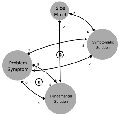
The example is based on the "Shifting the Burden" archetype. The first version looked like this:

The structure of this CLD archetype is not very obvious. Edges are overlapping, making understanding unnecessarily difficult.
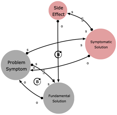
Using the above, select the top and the right node:

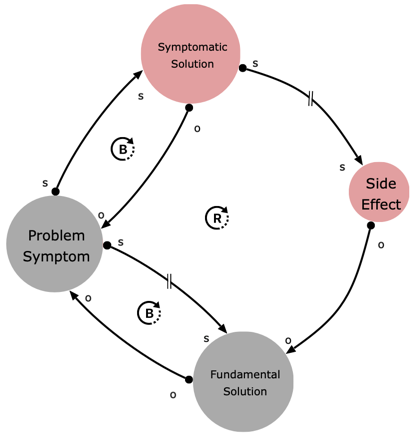
Now press [TAB] and the order of the two selected nodes is exchanged, resulting in a different positioning of these nodes in the internal order. In this example, they simply exchanged their location as well.

Now the structure becomes clear. The edges are no longer overlapping and the three loops become visible.
